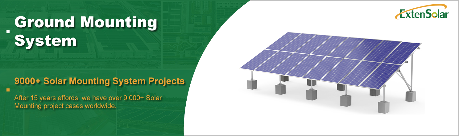
Details
| Surface Treatment |
Anodized |
Material |
AL 6005-T5 or cusmtom |
| Place of Origin |
China |
Installation Site |
Open Field |
| Brand Name |
Exten |
Model Number |
A02-1 |
| Standard |
|
Certificate |
AS/NZS1170.2/CE/ISO |
| Wind Load |
60m/s(196.85ft/s) |
Module Orientation |
Landscape Portrait |
| Wind speed |
Yo 60m/s |
Max Snow Load |
1.4KN/m2 |
| Snow Load |
1.4KN/m2(29.24psf) |
Service Life |
25YRS |
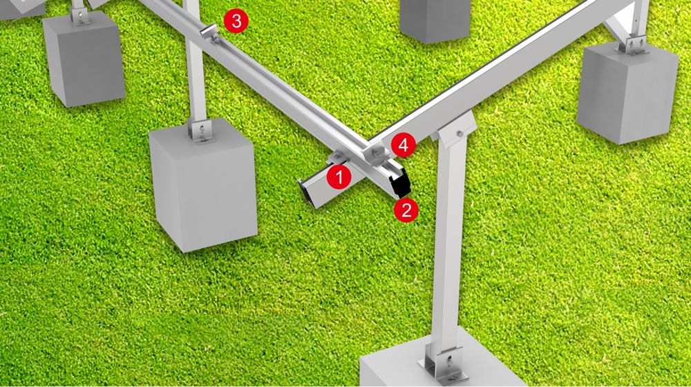
Component List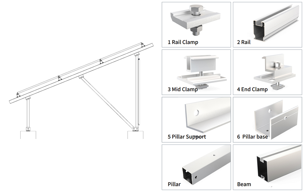
| Description |
Material |
Specificatioin |
Quantity |
| Rail |
AL 6005-T5 |
6000mm |
4 |
| Rail |
AL 6005-T5 |
3500mm |
4 |
| Beam |
AL 6005-T5 |
4000mm |
5 |
| Pillar |
AL 6005-T5 |
835mm |
5 |
| Pillar |
AL 6005-T5 |
1982mm |
5 |
| Beam Support |
AL 6005-T5 |
1960mm |
5 |
| Pillar Support |
AL 6005-T5 |
2500mm |
2 |
| Rail Splice |
AL 6005-T5 |
250mm |
4 |
| Rail Clamp |
AL 6005-T5 |
50mm |
40 |
| Pillar Connector |
AL 6005-T5 & SUS 304 |
120mm |
15 |
| Pillar Base |
AL 6005-T5 & SUS 304 |
140mm |
10 |
| End Clamp |
AL 6005-T5 & SUS 304 |
60mm |
16 |
| Mid Clamp |
AL 6005-T5 & SUS 304 |
60mm |
16 |
| Al Nut |
AL 6005-T5 |
20mm |
32 |
| Pillar Screw 01 |
|
|
24 |
| Pillar Screw 02 |
|
|
24 |
Elevated Ground Mounted Photovoltaic Overview
Elevated ground mounted photovoltaic refer to ground-mounted structures that raise the lowest point of photovoltaic modules to a clear height of two meters or higher above the ground. Unlike conventional mounting systems, which are typically 0.5 to 1 meter above the ground, this design is not intended to create a visually “towering” appearance, but rather represents a structurally optimized solution addressing multifaceted needs such as land-use diversification, ventilation and heat dissipation, operational and maintenance convenience, and adaptation to terrain. It retains the inherent advantages of ground-mounted systems—such as flexible orientation and reliable load-bearing capacity—while simultaneously unlocking multiple uses for the space beneath the solar farm by elevating the installation surface. This allows a single plot of land to simultaneously support power generation alongside functions such as agriculture, parking, or ecological conservation, making it a key technological direction for large-scale ground-mounted power plants amid increasingly scarce land resources.
Why Use Elevated Solar Panel Ground Mounting Frames?
The ground clearance of conventional racks only meets the basic requirements for foundation construction and ventilation beneath the modules. However, in the actual operation of large-scale power plants, this “ground-hugging” design has revealed an increasing number of limitations. Raising the modules to a height of over two meters essentially addresses the following core issues:
Enabling dual land use. The space beneath the elevated modules gains practical utility. In agricultural PV projects, harvesters and seeders can move freely beneath the modules, and normal cultivation and harvesting of crops throughout their entire life cycle remain unaffected. In parking lot PV scenarios, vehicles can park directly beneath the modules to seek shade and shelter from the rain, allowing the same plot of land to simultaneously generate clean electricity and provide parking services. This three-dimensional utilization model creates synergistic benefits from land that was previously used solely for PV, making it particularly suitable for regions with scarce land resources or high land costs.
Significantly improves ventilation and heat dissipation. The operating temperature of solar modules directly affects power generation efficiency; for crystalline silicon modules, the power-temperature coefficient is approximately a 0.4 to 0.5 percentage point decrease in power output for every 1°C increase in temperature. When raised, the space between the rear of the modules and the ground increases, allowing cool air to flow smoothly in from the bottom, creating natural convection that dissipates heat. In high-temperature regions, this cooling effect can effectively lower the operating temperature of the modules, resulting in a significant increase in annual power generation.
Completely resolves vegetation shading issues. The area near the ground is where weeds and shrubs grow most vigorously; especially during the rainy season, vegetation grows at an astonishing rate. Under conventional mounting systems, once vegetation touches the lower edge of a module, it creates localized shading, triggering the hot-spot effect that can lead to module damage or power degradation. When raised to over two meters, the height of the vast majority of ground vegetation remains well below the lower edge of the modules, fundamentally eliminating the risk of shading while significantly reducing the workload and costs associated with weed control at the site.
This significantly improves the efficiency of operations and maintenance (O&M) work. The space beneath conventional low-profile mounting structures is cramped, forcing O&M personnel to crouch or crawl to inspect cables, maintain connectors, and clean modules; prolonged work in such conditions is not only physically demanding but also inefficient. With the elevated design, personnel can walk upright beneath the modules, and tool carts and inspection equipment can move freely in and out, reducing the time required for routine inspections and maintenance by more than one-third. For large-scale power plants covering hundreds of megawatts, this efficiency gain directly translates into quantifiable savings in operating costs.
Adapting to terrain variations reduces earthwork requirements. On complex terrain such as hills and slopes, conventional mounting systems typically require extensive earthwork—including filling and excavation—to create a level installation surface. The elevated design, however, allows the length of support columns at different locations to be flexibly adjusted according to changes in topography. The module arrays span ditches and undulations vertically, eliminating the need for large-scale alterations to the original terrain. This not only saves on earthwork costs and construction time but also minimizes damage to surface vegetation and soil ecology.
Effectively mitigates the effects of water accumulation and humidity. The higher the bottom of the modules is above the ground, the less impact surface water accumulation and moist air after heavy rains have on the mounting system foundations, cables, and connectors. Improved air circulation also lowers relative humidity, reducing the risk of insulation degradation and corrosion in electrical equipment caused by prolonged exposure to high-humidity environments, which plays a positive role in extending the service life of the entire power plant.
CarbonSteel PV Ground Mounting Systems Installation
Step 1: Site Survey and Foundation Layout. Review topographic maps, geological reports, and meteorological data to determine the array orientation, spacing, and tilt angle. Mark the foundation locations point by point on-site based on the design coordinates. Use high-precision surveying equipment to ensure positional deviations remain within acceptable limits, and verify the diagonal and horizontal distances between adjacent points.
Step 2: Foundation Construction and Strength Verification. Construct the foundation according to the design plan, choosing from cast-in-place concrete foundations, precast concrete counterweights, or screw piles. Concrete foundations must be compacted and cured in accordance with specifications; formwork is removed once the strength reaches 75 percent of the design value. For screw piles, the final tightening torque is recorded in real time during the screwing process, serving as direct evidence for determining bearing capacity compliance.
Step 3: Column Installation and Elevation Fine-Tuning. Hoist the columns into position and secure them to the foundation. Use the adjustment nuts or telescoping joints on each column to fine-tune the top elevation of each column individually, ensuring that the tops of all columns in the same row are on the same horizontal plane. Monitor the entire process with a level, controlling elevation errors within ±2 millimeters.
Step 4: Assembly of Main Beams and Support Structures. Install the main beams onto the connection brackets at the top of the columns, then install the transverse braces, diagonal braces, and cross-bracing to form a stable spatial frame. Tighten all bolts to the design torque values and mark the torque settings. Periodically verify the overall dimensions and diagonal errors of the frame to ensure the structure is square and free of distortion.
Step 5: Laying and securing the module rails. Lay aluminum alloy module rails on the main beams at the design spacing, adjusting the elevation and horizontal position of the rails to ensure a level installation surface. Secure the rails to the main beams using specialized fasteners to prevent slippage or displacement during operation.
Step 6: Positioning and Securing the PV Modules. Hoist the PV modules onto the rails in sequence according to the layout diagram, and secure them using specialized clamps and anti-loosening bolts. Handle the modules with care during installation to avoid bumping the edges or backs. Verify the accurate positioning of each module on the rails and ensure that the joint gaps are uniform and consistent.
Step 7: Grounding Connections and Final Inspection and Acceptance. Complete the grounding jumpers between all modules and the connection between the mounting system and the grounding electrode, then test whether the grounding resistance meets design requirements. Conduct a final torque spot check on all fastening bolts, organize construction records, test reports, and acceptance documents, clean up the site, and hand it over to the electrical installation team for subsequent work.
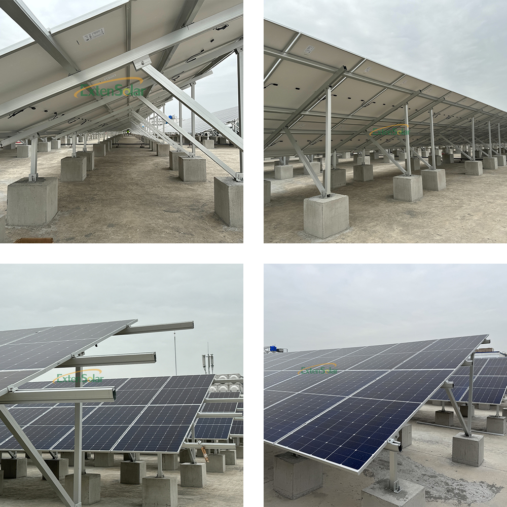
Helical Piles Ground Mount Solar Frames Case
FAQ
Q1: Is the wind resistance of tall mounting systems reliable?
A1: Yes, it is reliable. Wind resistance depends on the comprehensive design of the column cross-sectional dimensions, support system layout, and foundation burial depth—not simply on “height.” By adding diagonal braces, tie rods, and reinforced joint connections, tall mounting systems can fully meet design requirements for wind speeds of 160 kilometers per hour or even higher, ensuring structural safety.
Q2: By how much will foundation costs increase after raising the height?
A2: The foundation’s bearing capacity does indeed need to be correspondingly increased to resist greater overturning moments, and the cost increase typically ranges from 15% to 30%. However, a comprehensive assessment is required: the benefits derived from land’s mixed-use, labor cost savings from improved O&M efficiency, and reduced costs for weed control and vegetation management—these long-term benefits far outweigh the incremental foundation expenses.
Q3: Is this mounting system suitable for all site types?
A3: Not all sites are suitable. For projects with extremely high wind speeds, dense module arrangements, or shallow groundwater levels, the elevated design may face both technical and economic constraints. It is recommended to conduct a technical and economic comparison during the early project phase, taking into account specific site conditions and project objectives, to select the optimal height above ground.
Q4: What crops can be grown in the space beneath the structure?
A4: It is suitable for shade-tolerant or semi-shade-tolerant crops, such as certain leafy vegetables, medicinal herbs, or forage grasses. Specific crop selection should be evaluated based on local sunlight conditions, the light requirements of the crop varieties, and agronomic needs. The spacing and tilt angle of the support structure must also be coordinated with agronomic planning to ensure that both power generation and crop cultivation are effectively managed.
Q5: Will installation take longer than with conventional racks?
A5: The installation timeline is primarily influenced by the foundation construction method and site topography, and is not significantly related to the rack height itself. The number of components, connection points, and installation procedures for tall racks are essentially the same as for conventional racks. Provided that material supply and technical briefings are adequate, the construction schedule will not be significantly delayed due to increased height.


